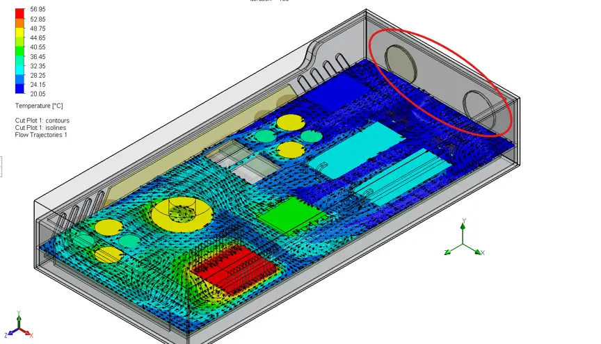
Traditional FEA tools estimate cooling with assumed coefficients - SOLIDWORKS Flow Simulation calculates actual airflow behaviour using CFD.
Repositioning a fan, adding a PCB, or rerouting cables can dramatically alter thermal performance in ways only CFD can predict.
A liquid-cooled enclosure project let engineers optimise cooling arrangements digitally, eliminating multiple physical prototypes.
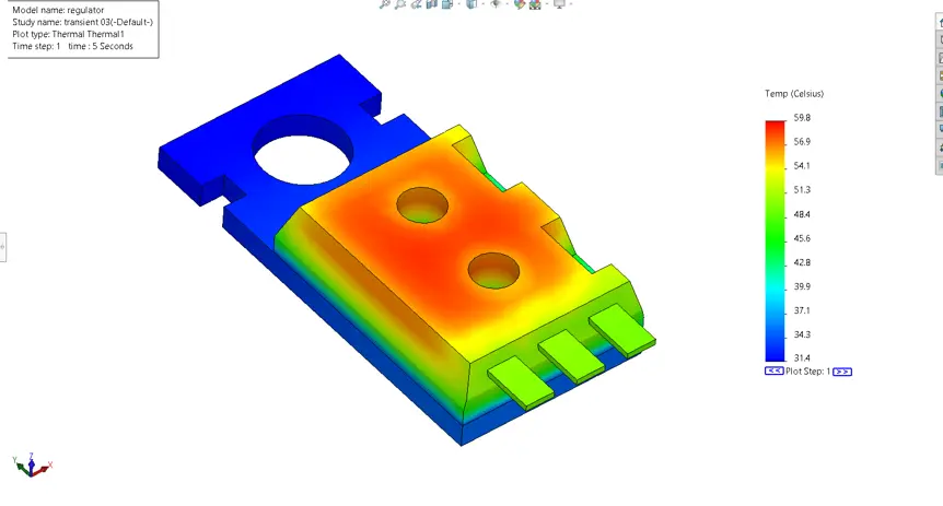
Flow Simulation delivers measurable data on velocity, pressure losses, stagnant zones, and transient heating - not just temperature plots.
Catching thermal issues during the design stage avoids expensive rework on imported electronics and custom-machined enclosures.

Operations Manager
When engineers design an industrial enclosure, most attention naturally goes to the electronics inside it. FPGA boards, power supplies, motor drives and communication hardware all have well-defined power requirements and thermal limits. Yet one of the biggest causes of overheating isn’t the components themselves, it’s the movement of air around them.
This is where I see projects become unnecessarily expensive. The structural design may be correct. The electronics may be correctly specified. The enclosure might even pass a traditional thermal conduction analysis. But once the first prototype is powered up, unexpected hot spots appear because nobody predicted how the air would actually move through the enclosure.
Traditional FEA packages are excellent at calculating heat conduction through solids. They can show how heat travels through aluminium, copper or steel, but they still need an assumed heat transfer coefficient to represent cooling by air. Choosing that value is often educated guesswork. Unless you know exactly how the air behaves inside the enclosure, you’re estimating one of the most important parts of the problem.
This is exactly where SOLIDWORKS Flow Simulation changes the engineering process.
Inside an electrical enclosure, heat is constantly transferred in several different ways:
Each of these mechanisms influences the final operating temperature.
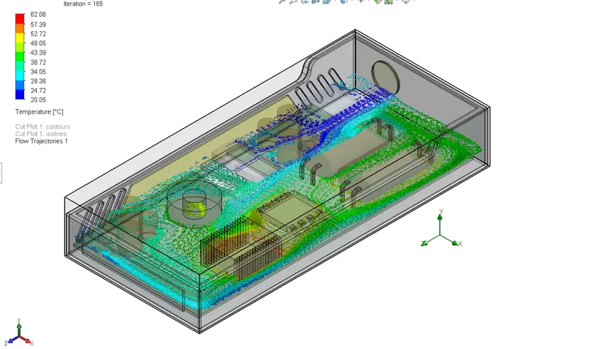
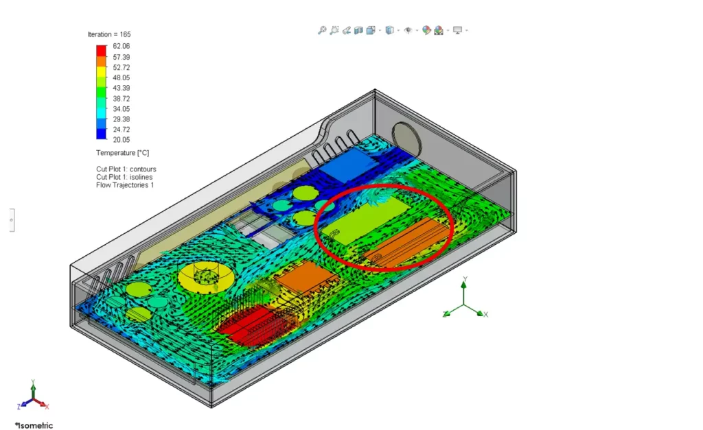
Instead of asking the engineer to estimate the cooling effect, SOLIDWORKS Flow Simulation calculates it using Computational Fluid Dynamics (CFD). It predicts the actual airflow inside the enclosure, whether that movement is caused by natural convection, cooling fans, pumps or external airflow.
The result is a complete temperature distribution throughout the enclosure rather than temperatures based on assumed cooling conditions.
Unlike a traditional thermal study where the cooling effect is represented by an estimated convection coefficient, Flow Simulation continuously calculates how air accelerates, slows down, recirculates and transfers heat throughout the enclosure. That means changes such as moving a fan or adding another PCB automatically change the airflow solution rather than relying on manually updated assumptions.
Many engineers have experienced the same situation.
A thermal analysis shows acceptable temperatures, but the physical prototype overheats.
The reason is rarely the material properties or the power dissipation figures. It is usually because the airflow inside the enclosure behaves differently from what was assumed. Choosing the right type of simulation study is often the difference between catching these issues early and discovering them on the prototype bench.
Small design decisions can have a surprisingly large effect:
Each of these changes alters the airflow path, which directly affects cooling performance. Without CFD, these effects are difficult to predict until expensive prototypes have already been built.
During a recent engineering assessment for a manufacturer developing a liquid-cooled electronics enclosure, we were asked to evaluate a liquid-cooled enclosure for high-power processing hardware.
The challenge wasn’t whether the heat exchanger could remove heat in theory. It was understanding how the complete cooling system would behave once multiple heat-generating devices were operating continuously inside the enclosure.
Before any simulation work started, we spent time defining the operating conditions.
Questions included:
Only once these questions had been answered could we build a representative Flow Simulation model.
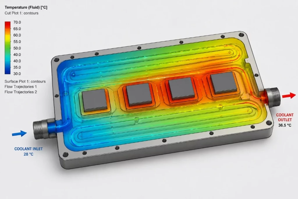
The simulation allowed the engineering team to visualise coolant flow, identify temperature hot spots, evaluate different flow arrangements and predict component temperatures during continuous operation, all before manufacturing a prototype.
Published case studies from manufacturers such as POLYRACK and ioSafe show similar results, where Flow Simulation resolved enclosure cooling challenges before any physical prototyping took place.
In several cases we adjusted the cooling arrangement digitally before any hardware had been manufactured, eliminating the need to evaluate multiple physical concepts.
One misconception is that Flow Simulation only produces colourful images.
The visual results are useful, but they are only part of the value.
Engineers can investigate:
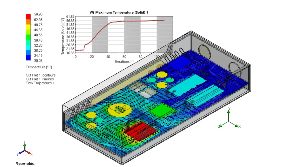
For enclosures with densely packed electronics, the Electronics Cooling Module adds dedicated tools for PCB thermal simulation, heatsink selection, and an expanded database of fans and interface materials.
This makes it much easier to compare multiple design concepts before manufacturing.
Rather than asking “Will this work?”, the question becomes “Which design works best?” That shift allows engineering decisions to be based on measurable performance rather than engineering judgement alone.
For South African manufacturers using SOLIDWORKS, prototype iterations are rarely inexpensive. Imported electronics, machined components and custom sheet metal all contribute to development costs and longer lead times.
By validating thermal performance during the design stage, companies can identify potential cooling issues while changes are still inexpensive.
In my experience, the biggest value of SOLIDWORKS Flow Simulation is not producing attractive temperature plots. It is providing confidence that the enclosure will perform as expected when real hardware is finally powered on. That confidence allows engineers to make design decisions earlier, reduce prototype risk and spend less time troubleshooting thermal issues after manufacture.
If your enclosure contains high-power electronics, airflow is no longer a secondary consideration.
Understanding how heat moves through air is often the difference between a reliable product and one that overheats during testing.
SOLIDWORKS Flow Simulation helps engineers move beyond estimated convection values and instead predict how heat, air and fluids interact within the complete design. For projects involving industrial control systems, FPGA hardware, power electronics or liquid-cooled assemblies, that insight can significantly reduce development risk before the first prototype is ever built. MECAD Systems offers dedicated Flow Simulation training to help engineering teams get started.
Share this post: