Sending a plastic part to the toolmaker without simulation risks costly geometry changes once tooling design has already started.
Unmerged bodies and tiny gaps between faces cause mesh failures - resolving these in CAD is far faster than restarting a failed mesh.
The Edit/Review tool and body-by-body isolation turn thousands of unmatched elements into an actionable checklist.
The Injection Location Advisor evaluates up to ten injection points automatically, with the option to exclude cosmetic and functional surfaces.
After a study completes, the built-in adviser flags manufacturability issues and suggests specific geometry changes to resolve them.
Applications Technician
Hidden inefficiencies in the design office often go unnoticed until a part hits the toolroom. A designer spends days perfecting a plastic component, exports the STEP file, and sends it for manufacturing, only for the toolmaker to reply that the part cannot be moulded.
Fixing the geometry at this stage can add significant cost and delay, particularly once tooling design has already started. This is the trial-and-error tax. By utilising SOLIDWORKS Plastics simulation during the design phase, designers can take ownership of the manufacturing outcome. It allows them to validate designs against the harsh realities of the injection process before the first rand is spent on specialised tooling.
This article looks at four practical ways engineering teams can use SOLIDWORKS Plastics to identify moulding problems earlier and send more manufacturing-ready designs to the toolmaker.
One of the most common causes of problems when setting up a plastics simulation is poor geometry preparation. Designers often build complex plastic components as well as multi-body parts in CAD. If they forget to merge a boss or a rib properly, or if there are tiny gaps between these bodies, the mesher cannot create a continuous volume. This results in overlapping elements or unmatched elements across the boundaries. Even if a study can be run with unresolved mesh issues, the results may not represent the intended geometry correctly.
Before starting the simulation, it’s worth spending time checking the CAD geometry carefully. Designers must ensure that all faces meant to be in contact are perfectly flush. Taking the time to resolve these geometric inconsistencies in the CAD model is far faster than waiting for a complex mesh to fail and having to start over.
When a mesh does fail, finding the exact location of the error in a complex part can be daunting. We encountered this recently with a South African packaging manufacturer setting up a fill analysis on a complex multi-body part. The mesh generation was failing due to geometry conflicts.
Upon reviewing the file, the diagnostic tool flagged nearly 3,000 unmatched elements. Because the part was complex, there was no immediate quick fix.
By testing each solid body individually, we found that they meshed perfectly on their own, meaning the errors stemmed entirely from the interfaces between multiple unmerged bodies. To locate the exact physical gaps, users should use the ‘Edit/Review’ mesh option and examine the ‘Overlap Region’. Breaking the problem down body by body turns a massive list of errors into an actionable checklist.
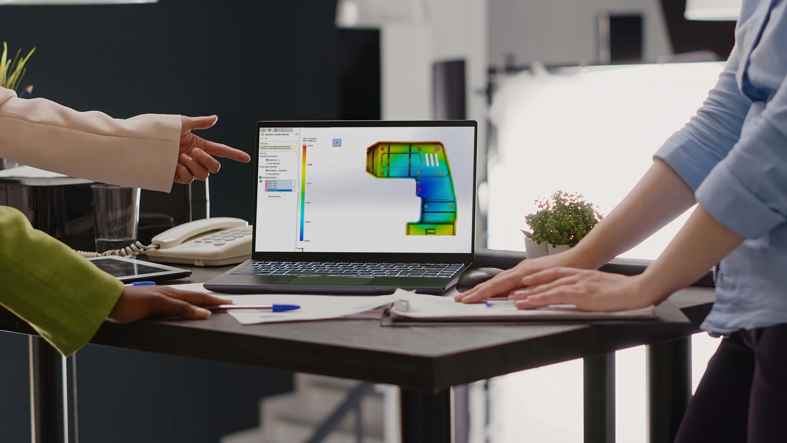
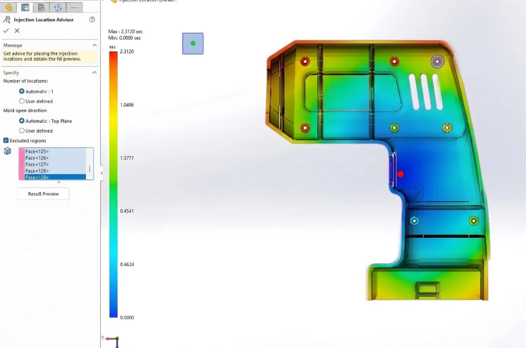
Gate placement can have a major influence on how successfully a part fills, particularly in complex components where several possible injection locations exist. If a gate is placed incorrectly, it can cause premature freezing, excessive injection pressure, and severe cosmetic defects. Instead of leaving this critical decision to the toolroom, designers should leverage the Injection Location Advisor PropertyManager directly within their plastic injection moulding design environment.
The software automatically scans the model geometry, the specified material, and the mould open direction to identify up to ten suitable injection locations. A highly useful feature within this tool is the ability to select excluded regions. This allows designers to block the advisor from placing gates on cosmetic faces or critical functional surfaces where a blemish would be unacceptable. By running a quick result review, the designer can see a preview of the fill plot. This gives the designer an early indication of whether the proposed gate location is likely to produce a balanced fill before committing to the final tooling.
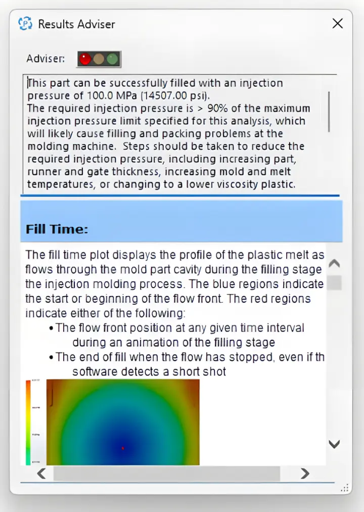
Even with advanced simulation, interpreting the data can sometimes be challenging. Designers should make it a habit to refer to the built-in Results Adviser after running their studies. This feature analyses the calculation data and provides practical design advice and troubleshooting tips for potential problems.
The adviser checks manufacturability factors like fill time, pressure distributions, and nominal wall thickness. If an issue is detected, it offers clear, actionable steps on how to resolve it within the geometry.
These recommendations shouldn’t replace engineering judgement, but they provide a useful starting point for investigating why a study is producing a particular result.
Taking greater ownership of a design means considering how it will be manufactured before it reaches the toolmaker. SOLIDWORKS Plastics gives designers a way to investigate potential moulding issues while geometry changes are still relatively inexpensive. By resolving geometry overlaps early, identifying the correct gate locations, and relying on the Results Adviser for troubleshooting, engineering teams remove the guesswork that causes costly tooling changes and production delays.
Ultimately, this proactive approach closes the gap between the CAD environment and the physical shop floor, saving both time and budget.
SOLIDWORKS Plastics doesn’t replace the experience of a skilled toolmaker. What it does is give designers much more information before that conversation begins. By identifying geometry problems, evaluating gate locations and understanding filling behaviour earlier, engineering and manufacturing teams can solve potential problems while changes are still inexpensive rather than after tooling has already started.
Share this post: