Feed screw pockets require a product to move along a helix while rotating about its own axis - a motion no standard SOLIDWORKS feature can produce.
Segment-by-segment sweeps, hand-placed lofts and surface stitching. Slow, fragile, and still only approximations.
The MECAD Feed Screw add-in generates accurate pocket geometry from four inputs: product body, shaft, helix and rotation point.
Design the screw for you. Pitch, rotation and clearances remain engineering decisions.
A surface-to-solid workflow using the Construct Surface tool produces a machinable solid ready for CAM toolpaths.

Applications Technician Certified SOLIDWORKS Expert (CSWE)
A feed screw does three jobs on a packaging line: it spaces products out, it times them into the next station, and it often turns each product into the right orientation on the way. It is also one of the most awkward parts to model in SOLIDWORKS.
I am an Applications Technician at MECAD Systems and a Certified SOLIDWORKS Expert. I presented our July webinar on the MECAD Feed Screw add-in, and I support the engineers who use it, so I see both where it saves time and where people get stuck. Here is the honest version.
The pocket of a feed screw is created by a product doing two things at once. It moves along the shaft, following the pitch of a helix, and at the same time it can rotate about its own axis. That second motion is the problem. A sweep can twist its profile, but the twist happens about the path itself. A feed screw pocket needs the product to turn about its own upright axis, perpendicular to the shaft axis, and no standard feature produces that motion.
For a plain round bottle you can approximate the pocket and get away with it. For a non-round product, an oval bottle, a rectangular pack, a container that must present its label to the next station, the true pocket shape is beyond the native feature set. The usual workarounds are sweeps built segment by segment, lofts between hand-placed sections, and surface stitching. They are slow, they break when the design changes, and the result is still an approximation. The pocket is the part that holds and steers the product, so pocket accuracy is the whole point of the exercise.
The MECAD Feed Screw add-in runs inside SOLIDWORKS as its own command tab. You model four things with ordinary features, and the add-in generates the screw from them:
Two settings matter most. Path coarseness sets how often a cut is taken along the path; the default of 5 degrees is fine for most work. Body rotation angle sets how far the product turns about its own axis over the length of the screw, for example 90 or 180 degrees, and you can set where along the path the rotation starts and ends. The add-in then subtracts the product body from the shaft at each step along the helix. That is the feed-plus-rotation geometry a manual cut-sweep cannot produce.
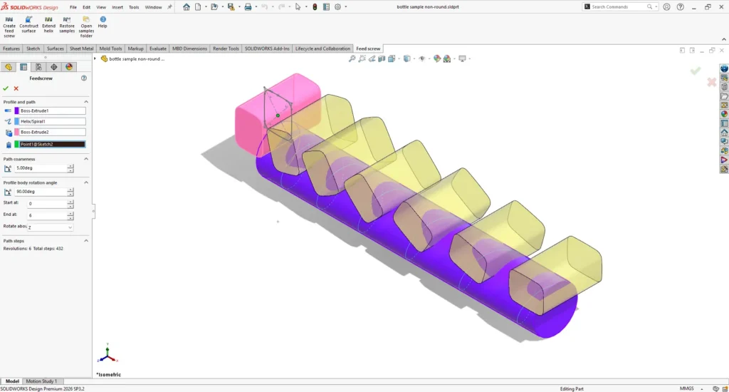
The add-in does not design the screw for you. The pitch, the feed rate, the rotation the product needs and the clearance between pockets are still your decisions. What it removes is the manual modelling that sits between those decisions and a finished screw, and it generates the screw in a fraction of the time it takes to build one by hand with sweeps and lofts.
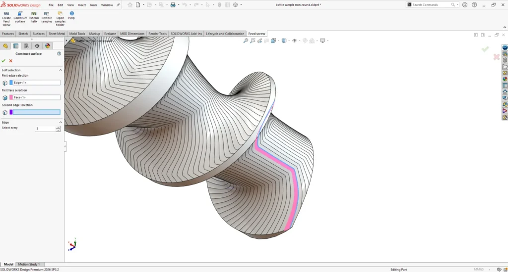
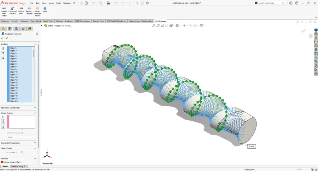
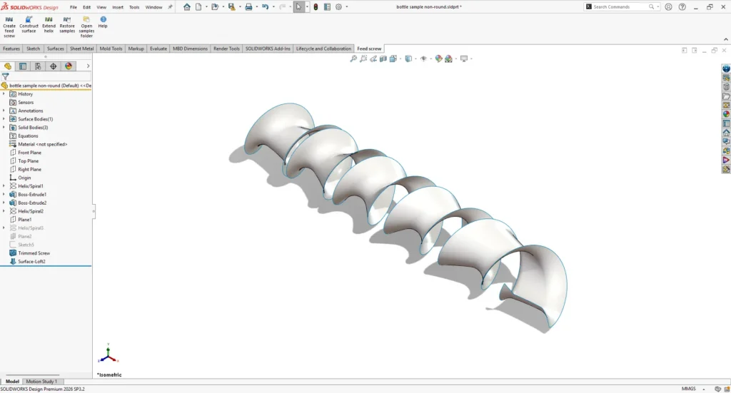
On simple screws the add-in can form the finished solid directly. On complex screws the better workflow is to generate the cut surfaces first, check them, and then build the final flight with the add-in’s Construct Surface tool: you pick the cut edges to loft through, and every second or third edge is usually enough. The result is one continuous surface. Trim it, use the Intersect tool to turn the surface and the shaft blank into a solid, and send it to CAM for toolpaths.
One case I showed in our July webinar makes the point. A packaging-machinery manufacturer had a screw where a helix had been converted to a spline, and the spline was carrying about 39,000 points. The part took about three and a half hours to regenerate, so every design change meant a three and a half hour wait to see the result. Simplify Spline brought the same curve down to about 600 points, and regeneration came back to a workable time with an acceptable result. A few rules prevent that kind of pain:
If you would rather watch this than read it, our tutorial videos cover the full workflow:
The video shows the four inputs being selected and a screw generated from them. It will tell you whether the workflow fits your parts faster than this article can.
The add-in is used by SOLIDWORKS customers from South Africa to Europe, Turkey, India, China and the United States, and the enquiries we get follow a pattern. Engineers find our tutorial videos while searching for a way to model a feed screw, usually because their local reseller had no answer.
One overseas reseller told us buying the add-in for their customer was cheaper than writing their own. Some companies have kept a second CAD system running purely for screw design while everything else lives in SOLIDWORKS. I have not found another tool that generates this geometry inside SOLIDWORKS, and that gap is why the enquiries come from so far afield.
If you design feed screws, watch the tutorial videos on MECAD’s YouTube channel, or contact us at support@mecad.co.za for a demonstration on one of your own parts. Bring your ugliest screw.
Share this post: